For a realistic Augmented Reality (AR) scene, a depth map of the environment is crucial: if a real, physical object doesn’t occlude a virtual object, it immediately breaks the immersion.
Of course, some devices already include specialized active hardware to create real-time environmental depth maps – e.g., the Microsoft HoloLens or the current high-end iPhones with a Lidar sensor. However, Google decided to go into a different direction: its aim is to bring depth estimation to the mass market, enabling it even for cheaper smartphones that only have a single RGB camera.
In this article series, we’ll look at how it works by analyzing the related scientific papers published by Google. I’ll also show a Python demo based on commonly used comparable algorithms which are present in OpenCV. In the last step, we’ll create a sample Unity project to see depth maps in action. The full Unity example is available on GitHub.
Quick Overview: ARCore Depth Map API
How do Depth Maps with ARCore work? The smartphone saves previous images from the live camera feed and estimates the phone’s motion between these captures. Then, it selects two images that show the same scene from a different position. Based on the parallax effect (objects nearer to you move faster than these farther away – e.g., trees close to a train track move fast versus the mountain in the background moving only very slowly), the algorithm then calculates the distance of this area in the image.
This has the advantage that a single-color camera is enough to estimate the depth. However, this approach needs structured surfaces to detect the movement of unique features in the image. For example, you couldn’t get many insights from two images of a plain white wall, shot from two positions 20 cm apart. Additionally, it’s problematic if the scene isn’t static and objects move around.
As such, given that you have a well-structured and static scene, the algorithm developed by Google works best in a range between 0.5 and 5 meters.
Research: Depth from Motion
The research behind Google’s underlying algorithm was published by Valentin et al. in 2018 .
The essential parts are:
- Keyframe selection: Selecting previously captured images that are distinct. Their relative 6 degree of freedom (6DoF) movement is known thanks to the visual inertial odometry (VIO) / simultaneous localization and mapping (SLAM)
- Preprocess camera images to prepare them for matching.
- Keypoint detection and
- Keypoint matching between both images.
- Stereo rectification: undistort and align images to each other.
- Stereo matching between these selected images to create a disparity / depth map.
- Depth map densification to get a complete map, ideally matching edges in the depth map to edges in the RGB source image. I will not show code for this step in the article.
1. Keyframe Selection
Most relevant for an AR depth map is the currently visible live camera image. Therefore, Google’s algorithm compares this to its archive of previous camera images. But which of these older images to choose?
In general: the more the camera moved since the chosen frame, the better the depth accuracy – however, at the expense of that image being older and therefore introducing depth inconsistencies.
Thus, a compromise is necessary:
- Baseline distance in 3D between both frames: the larger, the better – but at least 4 cm.
- Area overlap: depth can only be directly computed for areas that are visible in both images. Thus, the minimum is 40% overlap; but again: the larger, the better.
- Errors: if the 6DoF has low confidence in its motion estimate, the image should not be chosen.
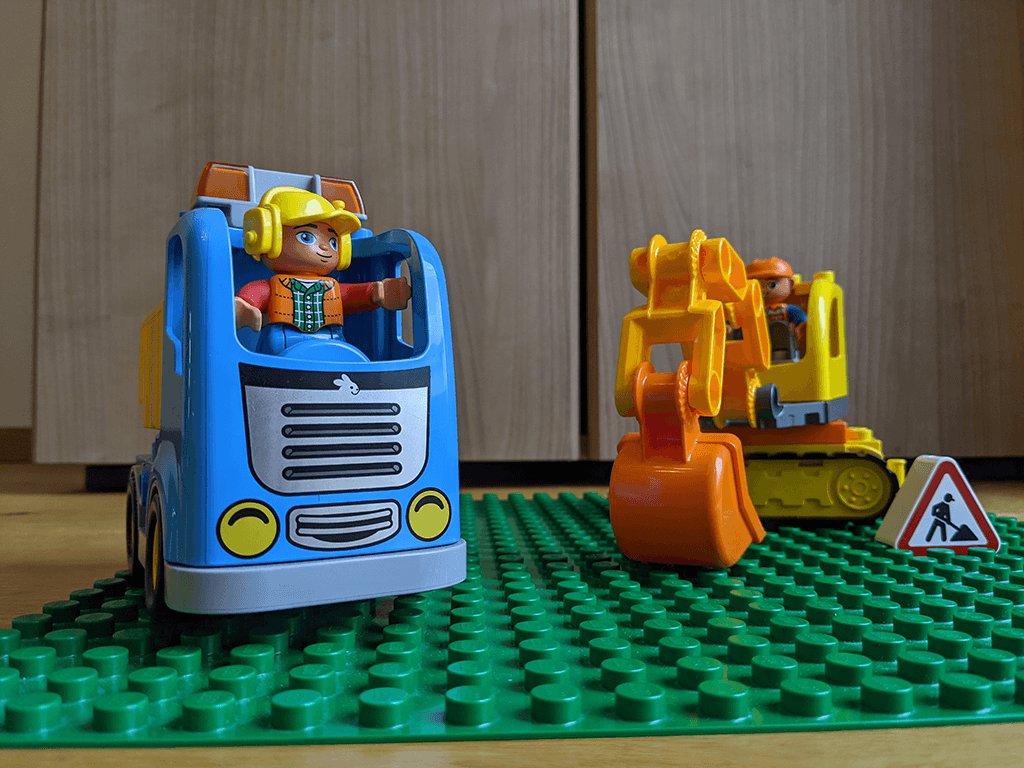
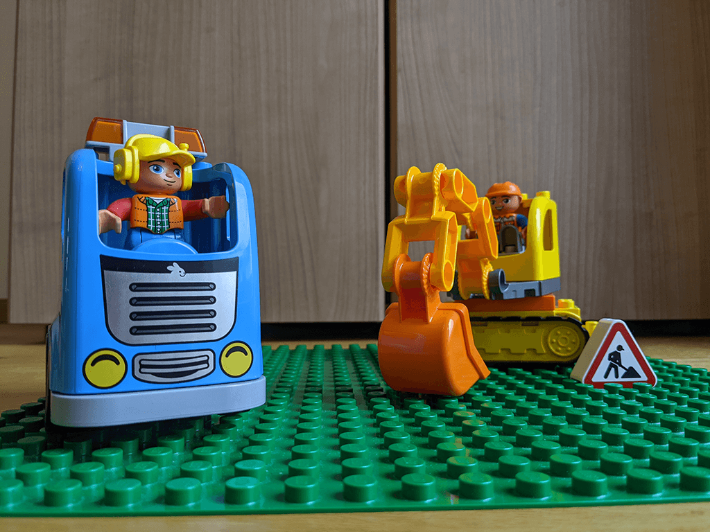
The algorithm developed by Google is optimizing many aspects of previous publications to run in real time. However, the basic principles are still the same when using code which is publicly available in OpenCV. For the following tests, I’ve taken these photos using a Google Pixel 4 smartphone. You can download the images if you’d like to run the code yourself.
2. Preprocessing Camera Images
The phone’s camera captures a 2D projection of the 3D space that we live in. Therefore, when you take a picture of the same scene from two different viewpoints, the captured pixels do not simply move to the left or right. Instead, pixels transform in multiple ways: they also rotate and scale.
Think of the extreme example of a fisheye camera, where the areas outside the camera’s center are distorted. To a lesser extent, the same also applies to a normal camera lens.
Loading and Comparing Left & Right Images
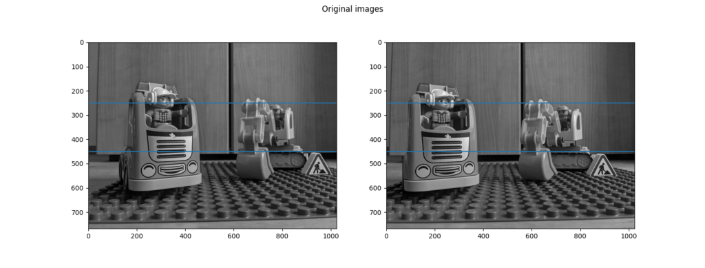
In the following picture, you see both keyframes next to each other. Two horizontal blue lines are drawn at the same y coordinate. If you look closely, you will notice that these lines generally hit the same objects in both pictures. However, there is a slight difference: sometimes, a specific feature is higher up in one image and lower in the other.

Below is the Python code used to draw the comparison picture seen above. I’ve tested it with Python 3.9, as well as the latest pre-compiled version of OpenCV 4.4 with extra (contributed) modules. Install this through:
pip install opencv-contrib-python
I also recommend using the Python extension in Visual Studio Code. Once you have your environment setup in place, execute the following code to show the demo images with the two blue comparison lines:
The full source code of the Python example is available on GitHub.
Article Series
In the next part, we’ll work on stereo rectification in Python and OpenCV, along with plenty of theory behind epipolar geometry and more!
- Easily Create Depth Maps with Smartphone AR (Part 1)
- Understand and Apply Stereo Rectification for Depth Maps (Part 2)
- How to Apply Stereo Matching to Generate Depth Maps (Part 3)
- Compare AR Foundation Depth Maps (Part 4)
- Visualize AR Depth Maps in Unity (Part 5)

