When dealing with Augmented and Virtual Reality, one of the most important tasks is capturing real objects and creating 3D models out of these. In this guide, I will demonstrate a quick method using the Intel RealSense camera to capture a point cloud. Next, I’ll convert the point cloud to a mesh using MeshLab. This mesh can then be exported to an STL file for 3D printing. Another option is visualization in 3D for AR / VR, where I’ll also cover how to preserve the vertex coloring from transferring the original point cloud to Unity.
Intel RealSense Depth Camera & SDK
Intel has recently discontinued the RealSense SDK for Windows. For the SR300 depth camera and the new Intel® RealSense™ Depth Camera D400, Intel has released a completely rewritten SDK on GitHub.
Unfortunately, the new SDK is by far not as powerful as the previous version (yet?). The old SDK included an example that was able to capture a whole 3D model by moving the camera around the object. At the time of writing, the new SDK only comes with 5 quite simple C++ example apps.
Still, it’s interesting to see how to convert a 3D point cloud taken from one point of view to a 3D mesh for visualization.
Capturing the Point Cloud
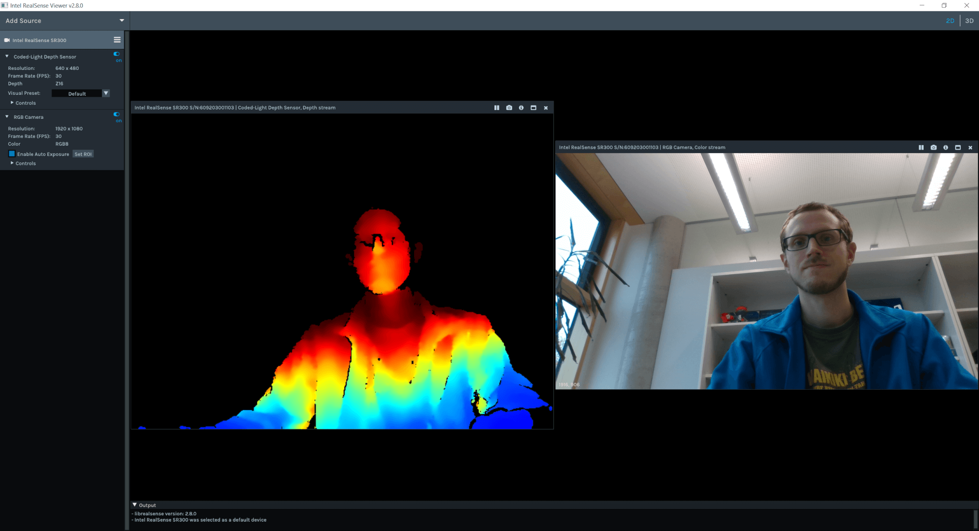
The Intel SDK comes with a very intuitive sample app called Intel RealSense Viewer. After connecting the RealSense camera, switch on both the “Coded-Light Depth Sensor”, as well as the “RGB Camera” in the panel on the right to see the output of both in separate windows.
The depth view is color-coded to show the depth; blue is closer to the camera; red is farther away.
Next, switch to the 3D view in the top right corner:
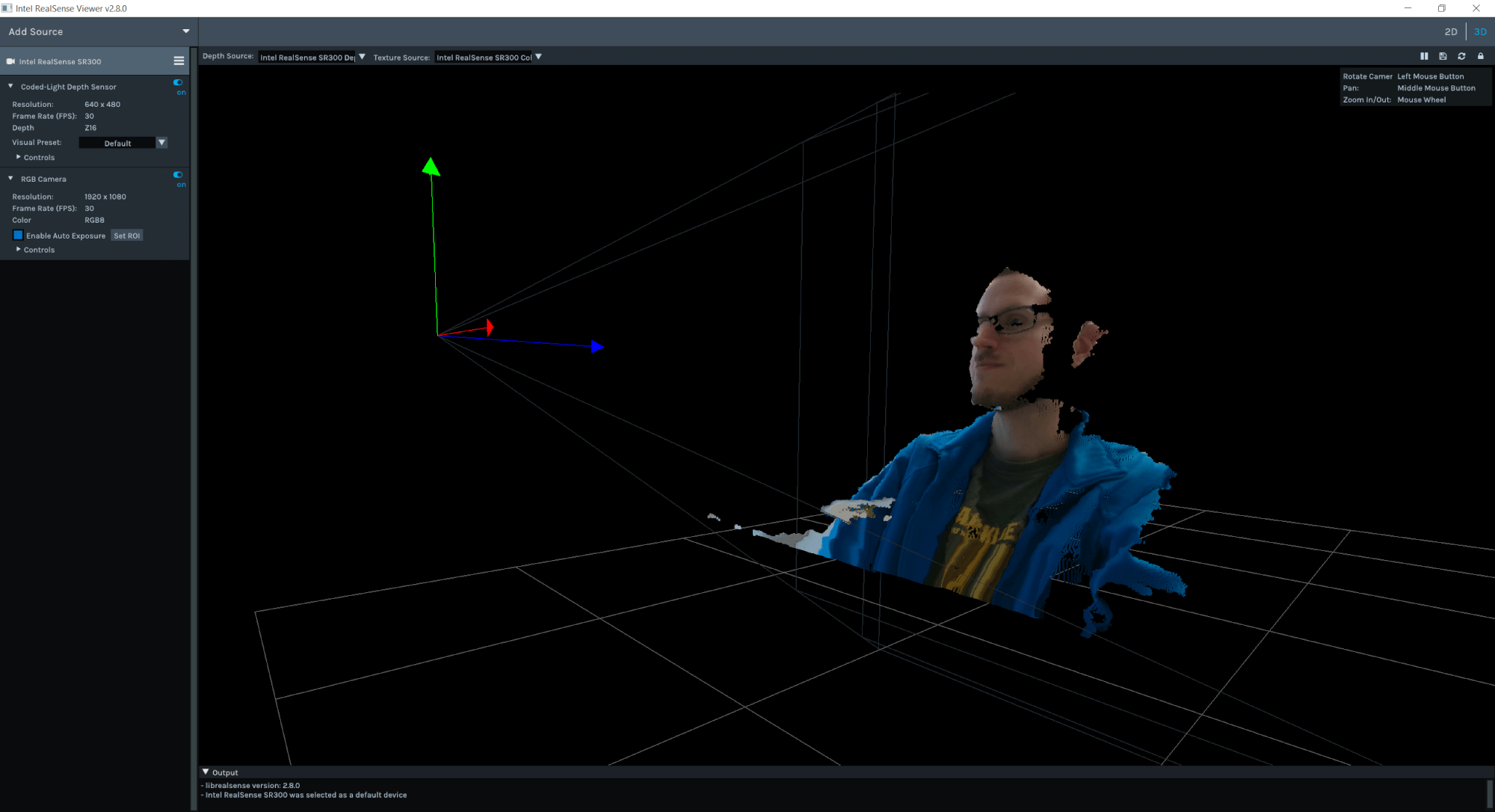
This combines the depth data with the captured color information to generate a colored 3D point cloud. By dragging the mouse in the 3D view, you can see the object from different perspectives.
In the top right corner, click the small save icon (“Export 3D model to PLY format”). PLY is a simple format for storing captured 3D data, which can be imported by a handful of apps.
Loading the Point Cloud in MeshLab
A great open source & cross-platform tool for working with 3D content is MeshLab. Create a new project and go to File > Import Mesh to select your PLY file. The app will instantly show the colored point cloud:
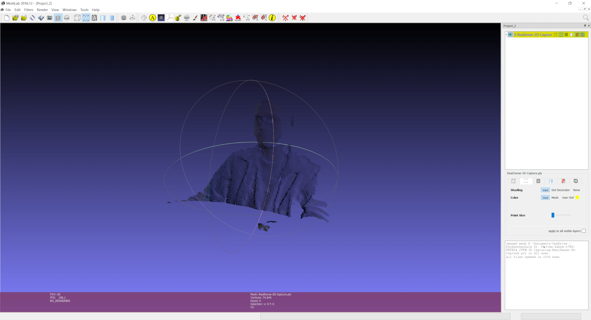
Try zooming in & out using the mouse wheel and rotating the view with the left mouse button. When you zoom in far enough, you see the individual colored 3D points / voxels.
The point cloud format is tricky to show for example using the HoloLens. Therefore, we need to convert it to a mesh with surfaces that can be easily rendered.
MeshLab provides several ways of converting a point cloud to a mesh. The instructions from fabacademy.org provide a good base for the following steps, as well as the MakerBot tutorial. The following steps worked well for me:
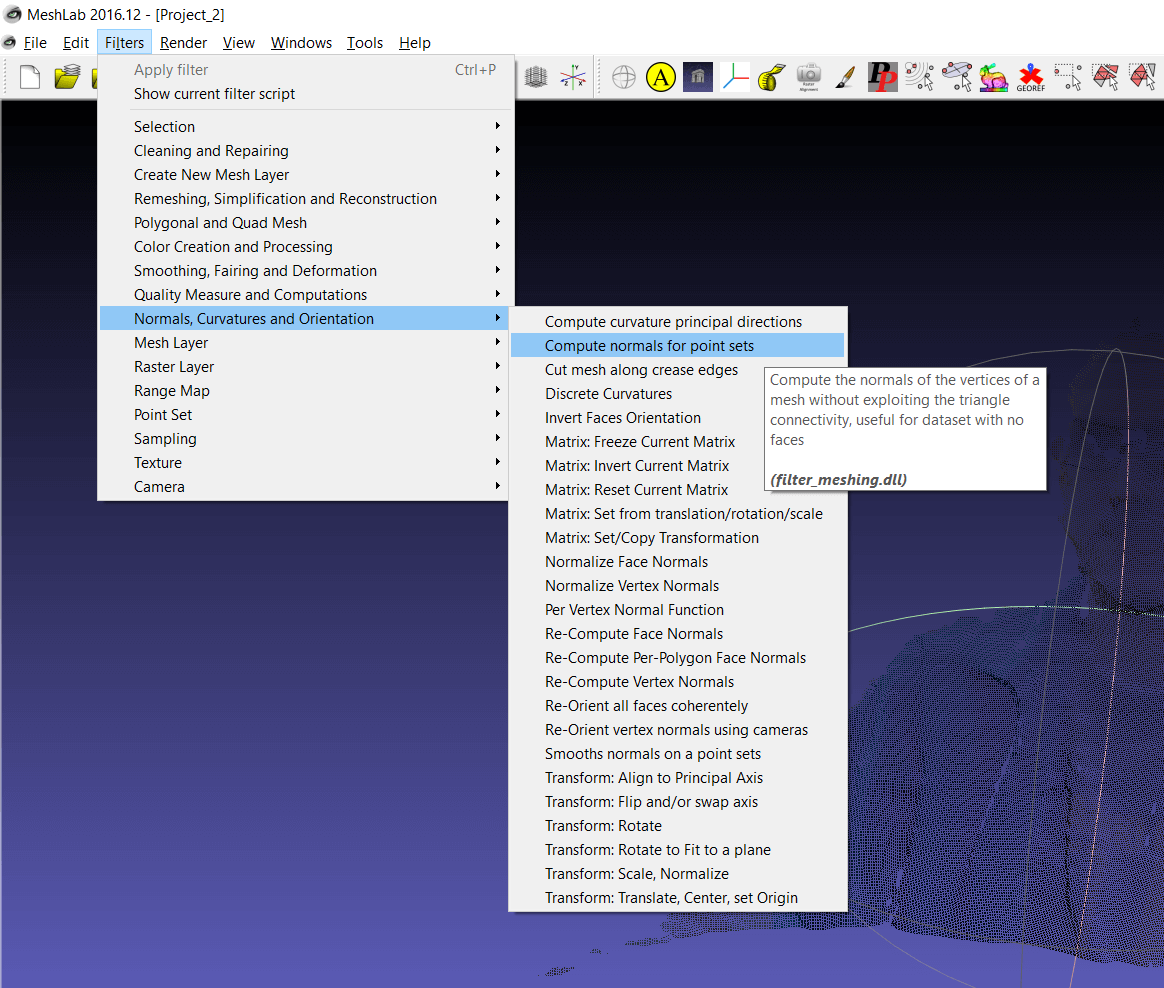
Creating Normals
First, you need to create normals for the individual points. MeshLab tries to find neighbors of the points to estimate the most likely surface, and then decide on a common surface orientation (what is inside, what is outside).
To start this process, use Filters > Normals, Curvatures and Orientation > Compute normals for point sets. The standard values should be OK for most scenarios; the preview shouldn’t change too much if you activate it. Click on Apply and close the window again.
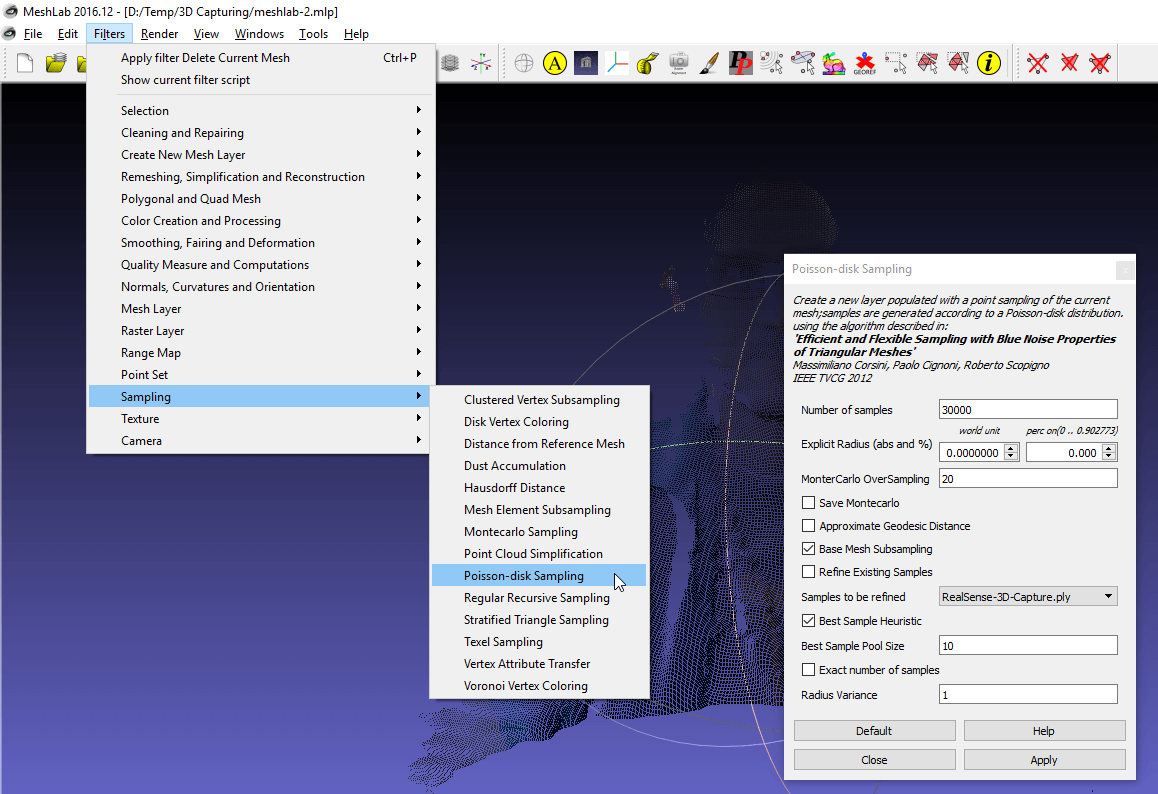
Simplification / Sampling
Depending on the use-case, you might want to reduce the complexity of the captured object. Especially for using the object in Augmented Reality with HoloLens or ARCore, it’s a good idea to simplify the point cloud.
Go to Filters > Sampling > Poisson-disk Sampling. Change to “Number of samples” to your desired final count – e.g., 30.000. Important: also select “Base Mesh Subsampling” – this is required for subsampling a dense point cloud.
An alternative would of course be to simplify the generated mesh after converting the point cloud to a mesh. Which works better depends on your data, but ultimately it shouldn’t make a significant difference.
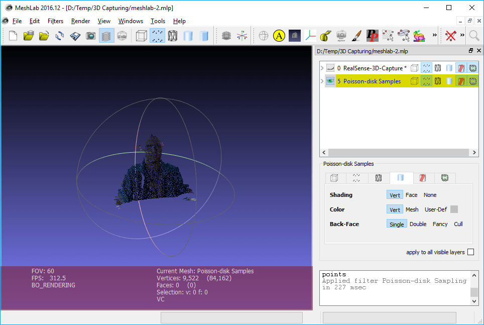
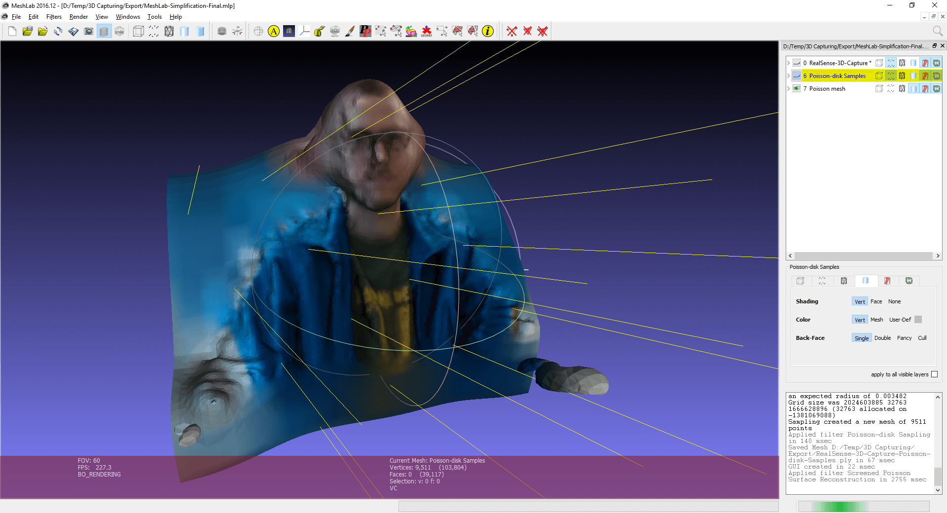
This process creates a second layer called “Poisson-disk Samples”. Deactivate the visibility of the original point cloud to check the simplified variant.
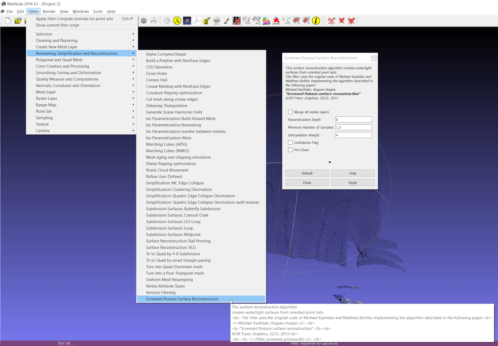
Converting the Point Cloud to a Mesh
Next, it’s time to convert the point cloud (with normals) to a mesh. Again, MeshLab contains a useful filter for this process. Choose: Filters > Remeshing, Simplification and Reconstruction > Screened Poisson Surface Reconstruction.
Depending on how noisy your data is, you can tweak the settings – for the point cloud captured by the RealSense Viewer app, the default settings are OK. When capturing in the RealSense Viewer, you can choose different modes suitable for various tasks (e.g., gesture recognition, face identification, etc.) – the “default” Visual Present already applies smoothing, so we don’t need to perform this step in MeshLab.
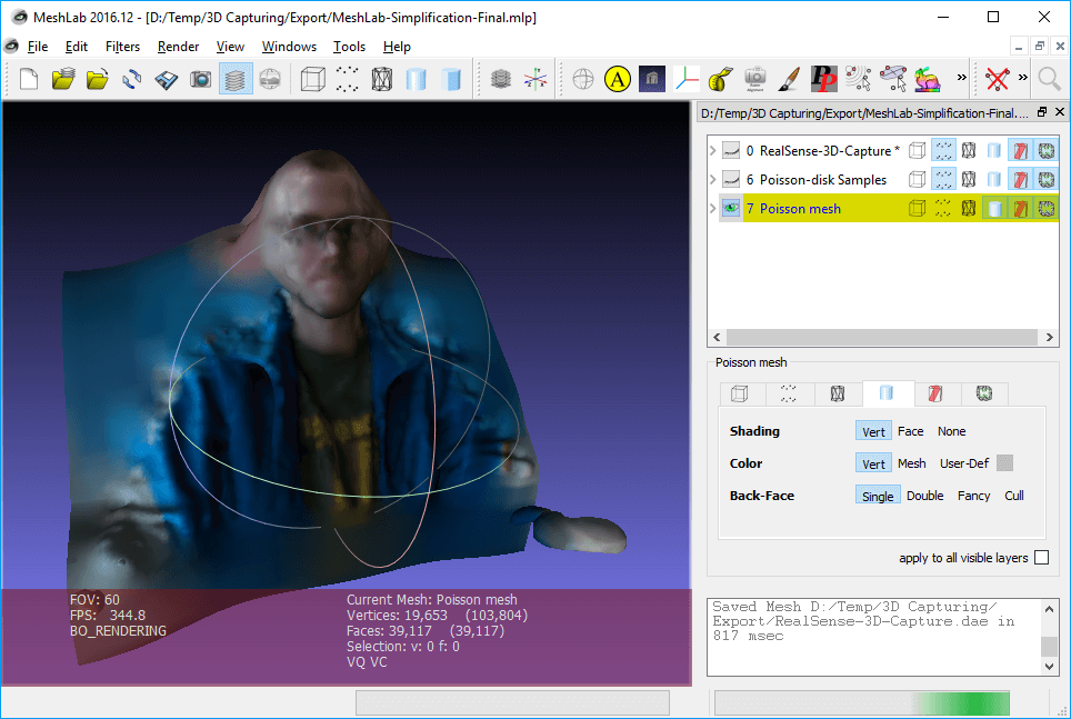
Click on Apply. The process takes a few seconds to complete. Afterwards, you’ll already see a full surface mesh in the 3D window of MeshLab. Close the filter window.
In my case, the 3D model appears rather dark. To better inspect your 3D model in MeshLab, turn around the default lightning by holding Ctrl + Shift and dragging with your left mouse pointer. The yellow light rays indicate the current light direction for the live 3D preview.
Exporting the Mesh: File Formats & Vertex Color
Finally, choose File > Export Mesh As… to save your generated mesh in the file format of your choice.
Currently, the colors of the point cloud are saved as per-vertex colors. You can easily check that by looking at the settings for the 3D preview – for the color, “Vert” is activated and no texture is present, meaning that the color of the mesh is coming from the vertices.
Exporting as .obj should include vertex colors – but for me, Unity doesn’t seem to import that. As a better transfer file format, I used the .dae format (Collada File Format, also see the answer on the Unity forums here).
Activating Vertex Colors with the Mixed Reality Toolkit Shader
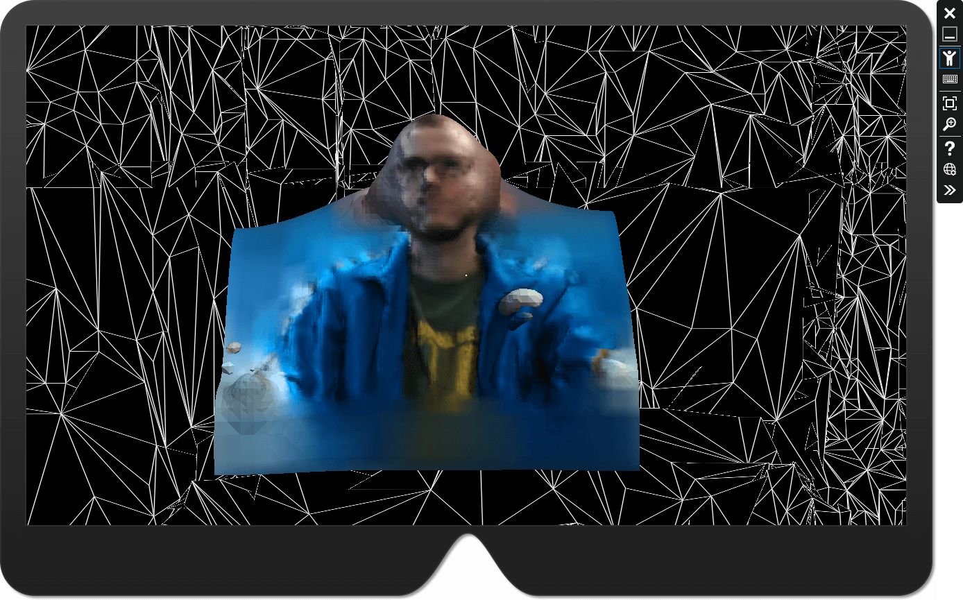
After importing the final mesh to Unity, you still need to activate vertex color shading. If you’re targeting HoloLens with the Mixed Reality Toolkit, it includes a shader that supports per-vertex-coloring.
Our captured 3D object is more or less just a plane, so use the 2-sided shader variant “Fast Configurable 2 Sided”. It allows us to see the object also when looking at it from behind.
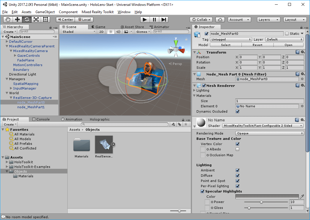
After choosing the shader for the object material, make sure you also activate the “Vertex Color” option in the “Base Texture and Color” region of the shader settings.
Wrap Up
That’s it! We’ve captured a 3D Point Cloud using an Intel RealSense camera and the latest SDK. Then, we’ve converted the point cloud to a simplified mesh. Finally, we’ve imported the object to a simple HoloLens-ready project and applied an optimized shader that also renders the vertex coloring originating from the point cloud.