The MySignals HW BLE v2 – eHealth and Medical IoT Development Platform for Arduino contains sensors that measure more than 20 biometric parameters. One of the most interesting is the Bluetooth LE SpO2 sensor. How to get started reading live data and visualizing it on the TFT display of the board?
What is the MySignals HW Kit?
The MySignals HW kit contains a shield that requires an Arduino Uno as base. In contrast to the (more expensive) MySignals SW kit, the HW kit is rather basic. Powering it up results in a white screen, instead of a nice interface on the screen. The rest is up to the software developer. As the development is based on Arduino, you need the latest version of the Arduino IDE.
Health SDK
The MySignals libraries are not available through the Arduino Library Manager repository, but need to be installed manually. The download link to the latest version is a bit hidden in the tutorial at step 5 – currently, the SDK is at version 2.0.1.
Extract the zip file. This gives you two folders: libraries and examples. The libraries folder contains 5 different libs – you need to install all of these through the Arduino IDE: Sketch > Include Library > Add .ZIP Library…. Afterwards, restart the Arduino IDE to also see the examples in File > Examples.
Bluetooth LE Pulse Oximeter
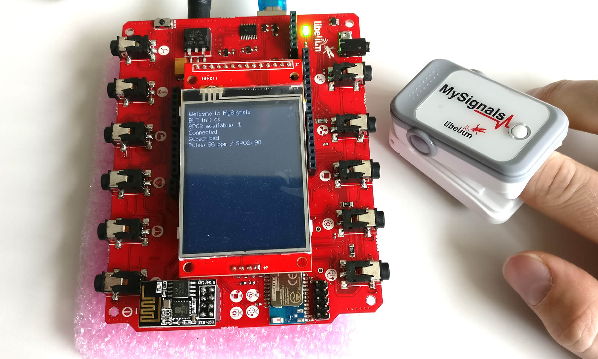
To get started, I decided to test the Bluetooth LE SpO2 sensor first. The small measurement device requires two AAA batteries and clips to your fingertip. By pressing the single button on the device, the sensor activates for a certain time, advertises itself via Bluetooth LE and starts measuring pulse and SpO2 through a (red) light sensor.
Unfortunately, the examples in the HW Kit SDK you just downloaded only include an example for the wired pulse oximeter, but not for the Bluetooth LE variant. The relevant example is available in the tutorial in section 6.2.2.4. You need the TFT example.
Be careful not to use the TFT BLE Example from the tutorial section 7.1.2, which also uses the SpO2 sensor – that version of the example misses a few lines of Bluetooth init code (to activate the UART Flow control) and fails to run. Only version 2.0 of the example works; version 0.1 in section 7.1.2 of the tutorial doesn’t.
Copy the code to your Arduino IDE. It doesn’t work out of the box, though – you still need to configure the code.
Pulse Oximeter Bluetooth MAC address
Close to the top, the example code contains a line “Write here the MAC address of BLE device to find”.
Unfortunately, the MAC address of the pulse oximeter isn’t printed on the device or listed anywhere on the kit. Therefore, you can use an app like BLE Scanner for Android:
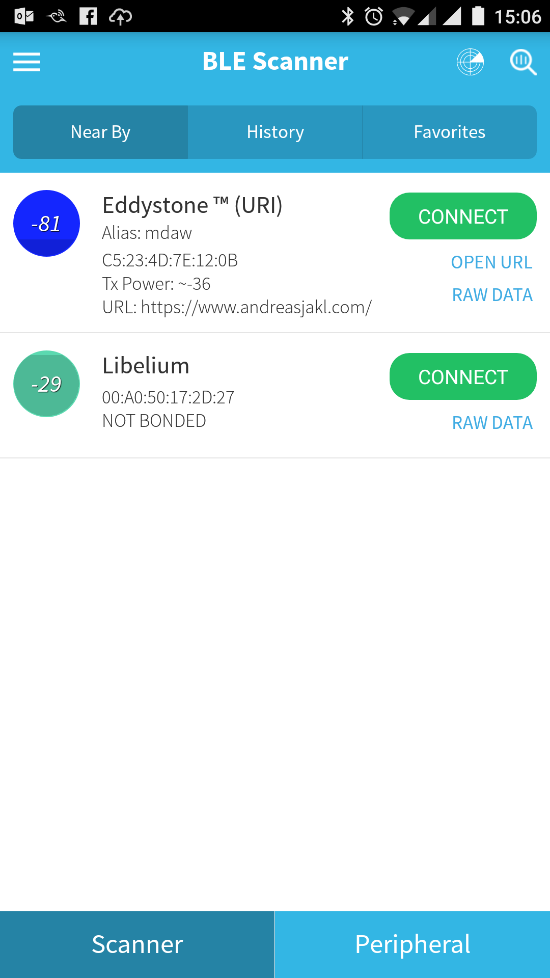
Once the app finds your SpO2 device (named Libelium), you can directly transcribe the MAC address – just remove the : separators. In my case, the corresponding Bluetooth MAC address to use in the Arduino code is:
char MAC_SPO2[14] = "00A050172D27";
Pulse and SpO2 Reading
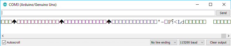
Now, compiling and uploading to the Arduino controller works. For some reason, the MySignals HW kit continuously outputs strange data over the serial port. However, as the tutorial example uses the TFT display for showing the measurements, we can ignore the serial output.
After running the example, press the button on the pulse oximeter and wait several seconds until the board finds the BLE sensor, connects, subscribes, and gets the real-time measurements.
In case you want to directly use the sensor, e.g., from a custom mobile app: a bit more information about the BLE profiles is published in a short PDF. The GATT profile information isn’t provided by the manufacturer, according to a recent forum post.