In part 1, we looked at how humans perceive lighting and reflections – vital basic knowledge to estimate how realistic these cues need to be. The most important goal is that the scene looks natural to human viewers. Therefore, the virtual lighting needs to be closely aligned with real lighting.
But how to measure lighting in the real world, and how to apply it to virtual objects?
Virtual Lighting
How do you need to set up virtual lighting to satisfy the criteria mentioned in part 1? Humans recognize if an object doesn’t fit in:
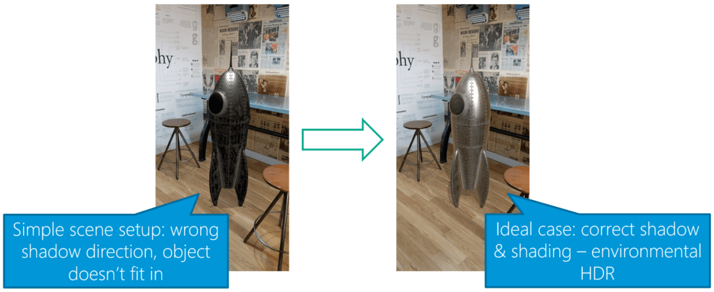
The image above from the Google Developer Documentation shows both extremes. Even though you might still recognize that the rocket is a virtual object in the right image, you’ll need to look a lot harder. The image on the left is clearly wrong, especially due to the misplaced shadow.
The importance of a proper shadow was already the topic of my first bachelor’s thesis, which I also briefly described in a previous blog post.
Environmental HDR?
But what is Environmental HDR? In the definition of Google, it is a combination of three different lighting properties: the main directional light, ambient spherical harmonics and HDR cubemaps.
Google released the following image through its blog to summarize the new features in ARCore that were released at Google I/O 2019:
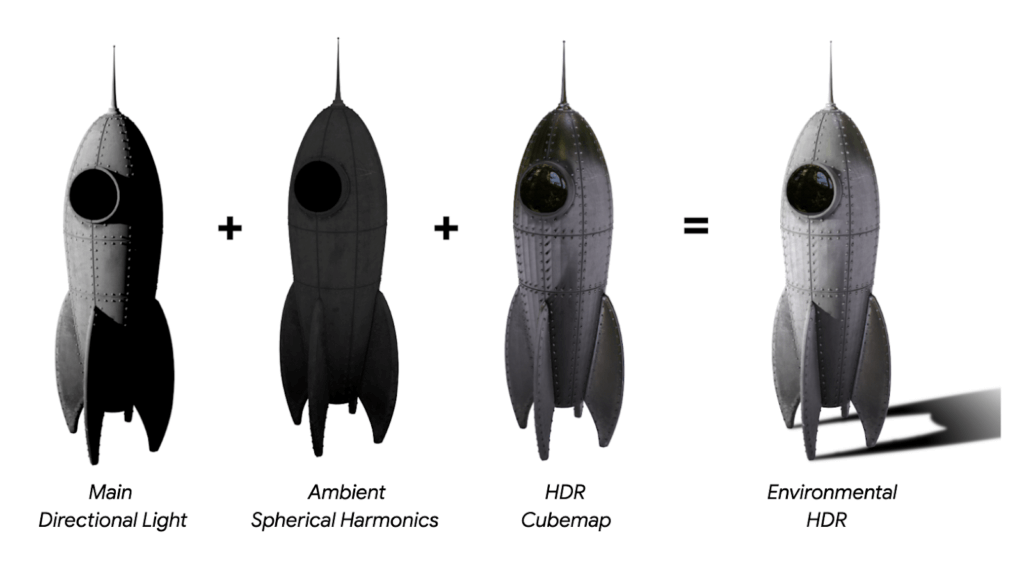
A directional light is easy to understand. An HDR cubemap contains reflections coming from different directions. But what are spherical harmonics?
The following image by Green et al. gives a good overview. The rows from top to bottom add more coefficients to model the light environment.

In the first row (also called “level” or “band”), the scene only has a constant light. The second row is still simple, the light is coming from opposite directions. In the next row, the light direction can already be expressed in more complex ways. The concept is also related to Fourier transforms used in JPEG compression; the higher frequencies you save, the more detailed information you can replicate.
A good example from the movie Avatar is also shown in a blog post at fxguide by Mike Seymour. Check it out to see a real-life example of spherical harmonics in action.
Capturing Environmental Light
Now we know about key properties of light. But how do you capture those from the real world? A very influential publication by Debevec et al. from Siggraph 1998 gives a good overview.
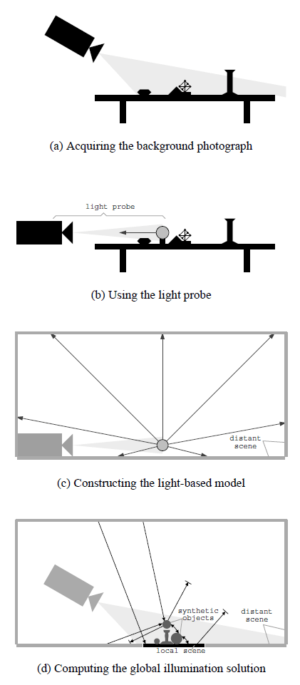
You can capture the light with a reflective steel sphere (called a “light probe”). Place this in the real world and take pictures both of the light probe as well as its surroundings (the background photograph). You can then use the light probe’s appearance (captured in HDR) to construct the light-based model. Apply this to a virtual object and render the virtual object into the real-world photograph.
What does a light probe capture look like? Based on multiple photos shot with different exposure levels, the limited color dynamic range and color reproduction capabilities of camera can still capture both details in the dark as well as the bright areas. It’s just split up into different images:

A good overview of the capture process is also part of the Google I/O ’19 talk about “Increasing AR Realism with Lighting”, which you can watch on YouTube.
Mobile HDR Challenges for Virtual Lighting
Capturing mirror spheres with multiple exposures is of course a great way to get an HDR lighting profile of the 360° surroundings. However, it’s a lot more difficult on mobile devices. In their DeepLight paper, LeGendre et al. from Google give a good overview of the challenges. The main ones are:
- HDR: Smartphone cameras are still small and not particularly good at handling dark scenes. They need longer exposure times. With handheld phones that are always moved by the users, this easily leads to blurry images.
If you then need to take several (for example 3) images from exactly the same viewpoint to combine them for a single HDR image, you need an even longer total exposure time. In real-time use cases like AR, you can only take a live camera image at a single exposure time. Thus, you lose the HDR aspect.

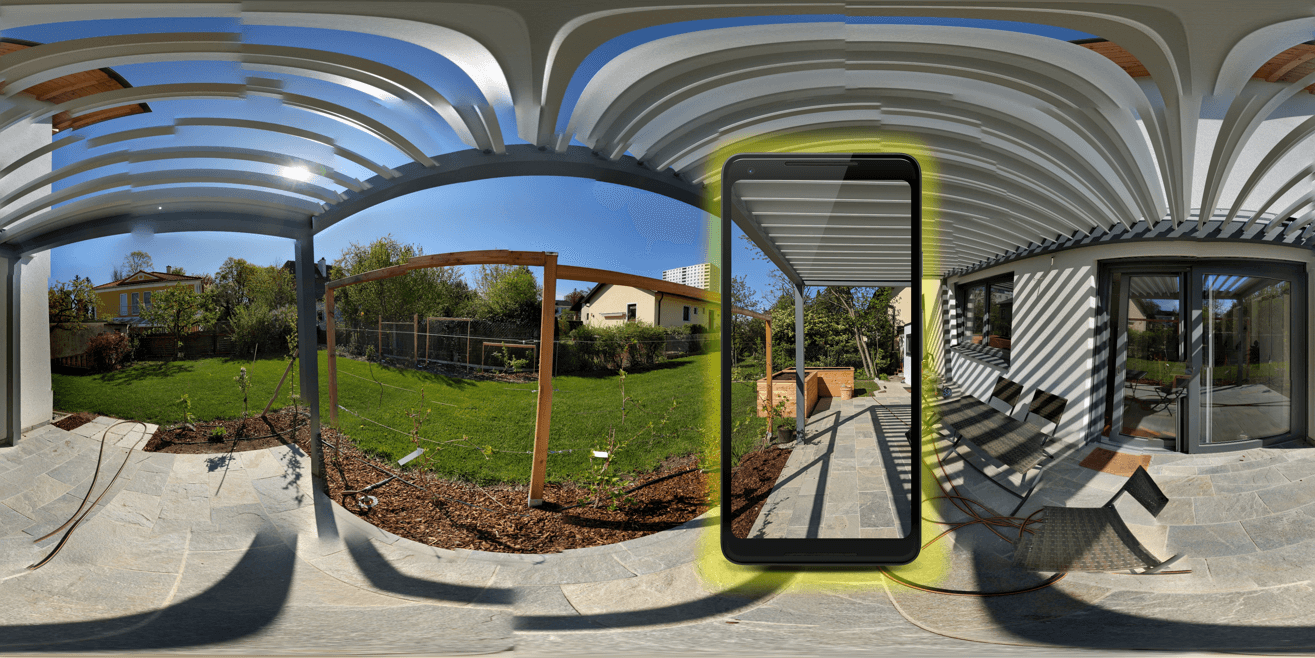
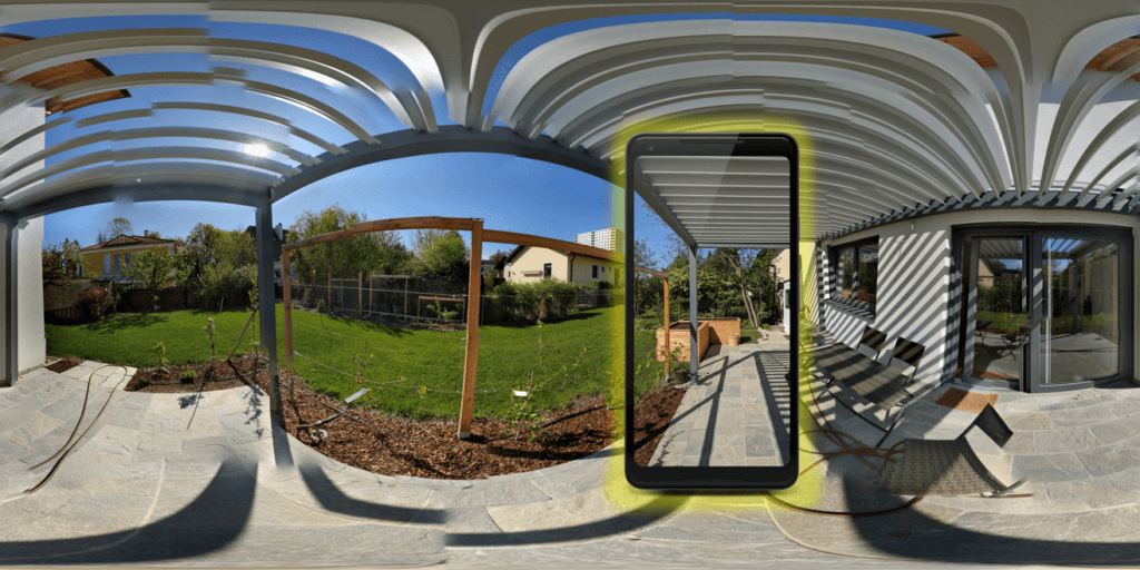
- FOV: Smartphone cameras have a limited field of view (FOV). Typically, only 6% of the 360° scene are visible. This makes it impossible to get an estimate of the global lighting situation.
Article Series
In the upcoming final part, we’ll look at how Google solved the issues mentioned above. Plus, how you can set up an ARCore project in Unity to visualize the environmental reflections!
