After importing the MRI / CT / Ultrasound data into 3D Slicer in part 1, we’re ready for the first 3D visualization inside the medical software through 3D Volume Rendering. This is a major step to export the 3D model to Unity for visualization through Google ARCore or Microsoft HoloLens, or for 3D printing.
Slices in 3D View
After optimizing brightness and contrast of the image data, the easiest way of showing the data in 3D is to visualize the three visible slices (planes: axial / top / red; sagittal / side / yellow; coronal / frontal / green view) in the 3D view. This gives a good overview of the position and the relation of the slices to each other.
Move the mouse over the small pin icon in one of the three slice views, and toggle the “Link the slice controls across all Slice Viewers” button, as well as the “Toggle slice visibility in 3D View” button.
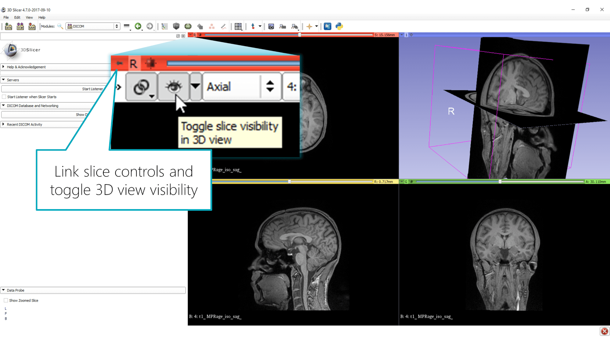
All three slices are now shown in the correct position and relation in the 3D view. Click and hold the left mouse button and move your mouse in that view to rotate it. Scroll the mouse wheel while hovering over one of the 2D slice view to change the visible slice. This change is then also immediately reflected in the 3D view.
Volume Rendering
While the 3D view of three 2D slices is great for locating details or for merging segmented 3D elements with the full image slice data, it gets really interesting when we proceed to a 3D visualization of the whole MRI / CT / ultrasound scan.
In 3D Slicer, switch to the module Volume Rendering in the toolbar. There, turn on the 3D view by selecting the volume in the drop-down and clicking on the closed eye symbol to open it.
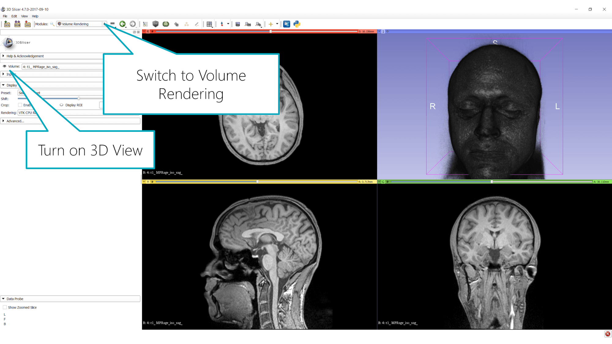
Of course, you can also deactivate the slice visibility of the three 2D slices by toggling the eye icon in the pin drop-down menu of the 2D views.
Background: T1 and T2 Weighting in MRI Scans
In general, in MRI images, bone and air are dark. This contrasts with CT images, where bone is white.
The data I’m visualizing in this tutorial is from a T1 weighting: dense bone, air and water are dark, while fat is bright. In the brain itself, gray matter is shown in gray, while white matter is whiter.
For T2 weighting, bone and air remain dark, gray matter remains gray. The other materials reverse their brightness compared to T1: water is bright, and white matter is a darker gray.
Adding Color and Structure
The resulting volume rendering of the scan generates voxels (=3D pixels) out of the stacked 2D slices. For this, Slicer needs to apply an opacity mapping, so that (e.g.) dark voxels are transparent and only the bright voxels remain visible. After all, if that wouldn’t be the case, you would only see a black box in the volume rendering.
The mapping that defines which brightness values should remain visible in the volume rendering and which should turn transparent depends on the visualization you’re trying to achieve. By default, the volume rendering uses a linear opacity mapping between black / transparent and white / opaque.
To adapt this, go to the Advanced… section of the Volume Rendering module and turn on Synchronize with Volumes Module. This re-uses the brightness and contrast that you manually or automatically defined in part 1 for the 2D slices.
Pre-Sets for Opacity and Color Mapping
To make the process of choosing the right mapping levels for volume rendering easier, 3D Slicer comes with several pre-sets.
In the Display section of the Volume Rendering module, click on Select a Preset. Choose for example MR-Default. This provides a generic color and opacity mapping for MR images, where tissue is shown in a tissue-like color and the brain is gray.
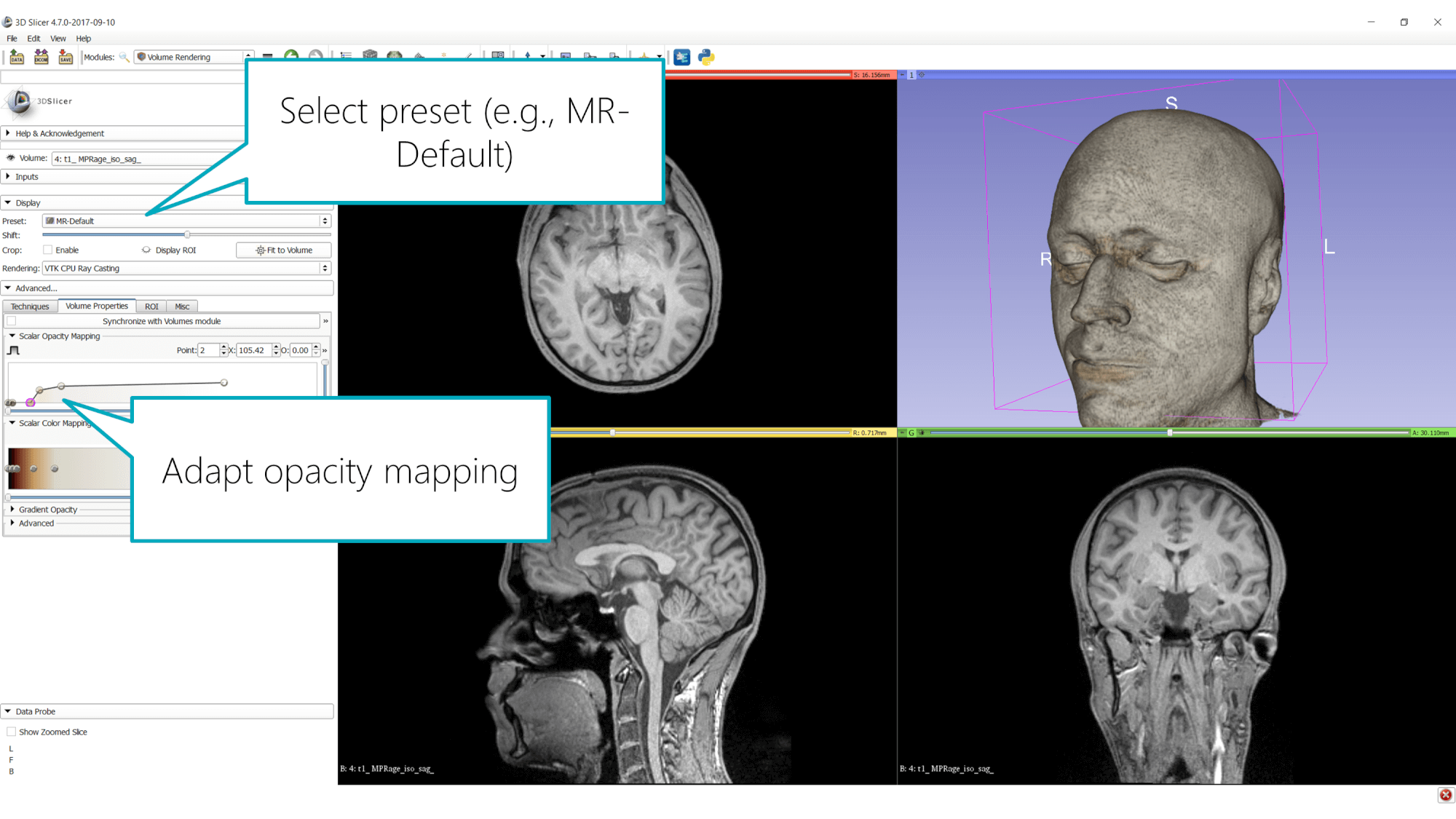
Of course, the exact mapping depends on the parameters that were used in the scan. By dragging the handles in the opacity and color mapping bars, you can adapt the transfer function to suit your data. You can also add and remove handles (middle mouse button). Make sure to minimize the noise around your volume and isolate the parts you want to remain visible.
Peek Inside your Head: Region of Interest
It is quite common to isolate a region of interest for the 3D visualization. In the simplest form, you just “cut” the 3D volume to peek inside your head.
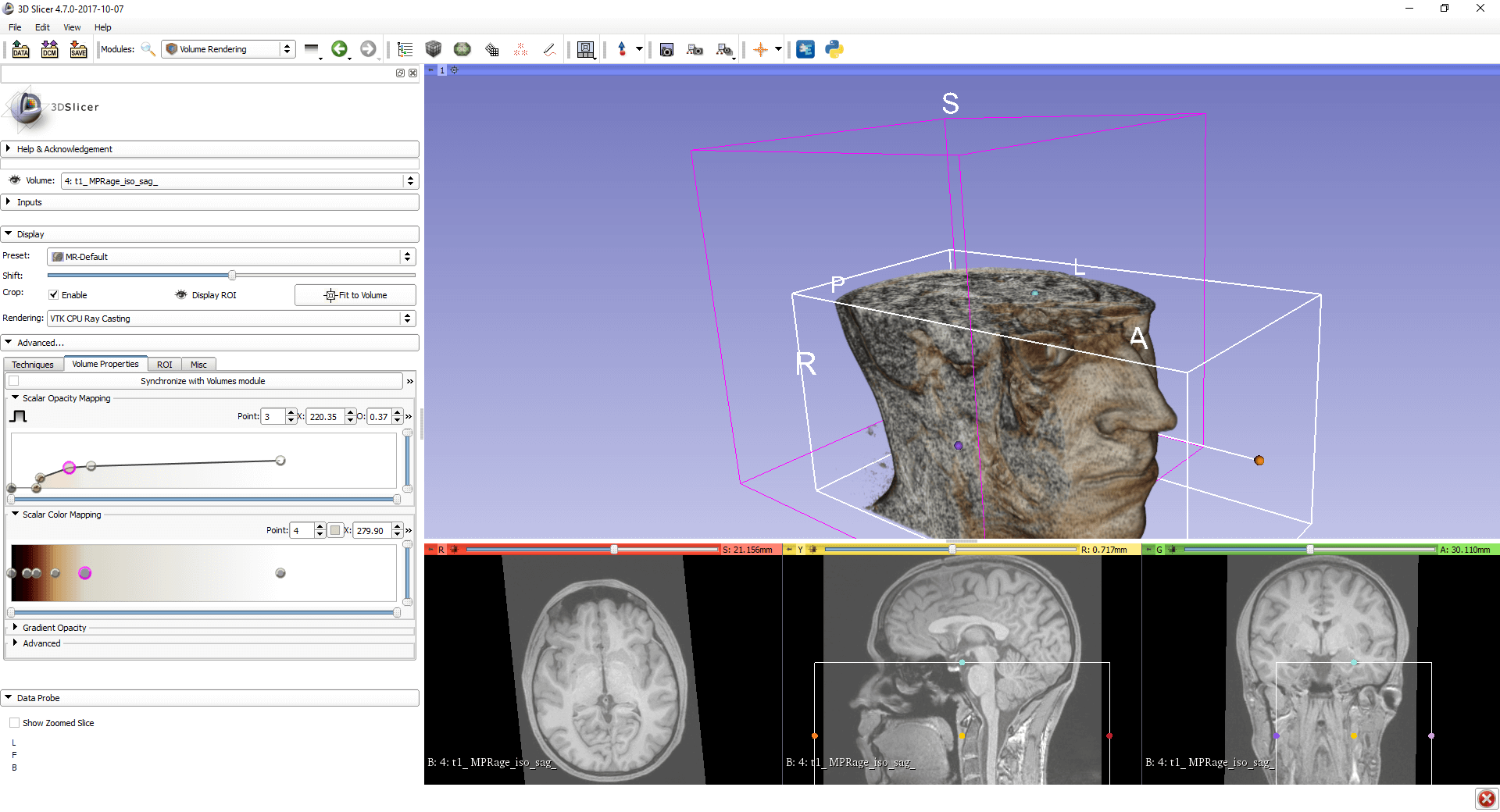
Activate the Display ROI eye toggle in the Display section of the Volume Rendering module. Now, a white box with colored sphere-like handles shows up in the views. Drag these handles to crop the 3D volume and to peek into your head. Experiment with the color and opacity mapping. This allows you to quickly hide parts of the scan in the 3D visualization.
What’s Next?
In the next part of the blog post series, we will create a 3D model based on the volume rendering. We’ll then use the model to show it in Augmented and Virtual Reality.